gum
Gum is a project that was long in the making. The short of it is that it is a 3d graphics/game engine using OpenGL inspired by my use of the Godot game engine. You can view a short video about it here.There are three main features that I would like to draw attention to.
- Scene Graph
- Dynamic Lighting
- My own math library
Scene Graph
A scene graph is a data structure used to organize objects in space. It works by "attaching" children to a parent object, and any scale, translation, or rotation which is applied to the parent is applied to all its children as well. One example of this might be "attaching" driver to a vehicle, such that whenver the vehicle moves, the driver inside of it will move as well.This type of abstraction makes a lot of sense for something like a video game or 3d scene, since often times objects are attached to other ones in the real world. Think about the driver and their car, or a person and their clothes.
The way this works is actually quite simple, but it requires a different way of thinking than I had used in the past. Basically any transformation on a 3D object can be represented as a 4x4 matrix (this also applies to 2D with 3x3 matrices). See this wikipedia article
To transform a single object, simply multiply all of its vertices by the transformation matrix, or the transform. We can chain these transformations by repeatedly multiplying by different matrices. This is how the final transformation of a given object is acquired, by multiplying through all the way up to its parent.
This allows the programmer to do things like attach a light to the camera in the video, or attach a camera to a player object, such that the camera can rotate in it's own coordinate system and it makes things like that so much easier.
This was the feature of the Godot game engine that I loved so much that I decided to implement it myself, and it was really eye opening for me.
Dynamic Lighting
This is a feature that I had avoided doing in the past with my previous openGL attemps, but this time I decided to go for it. The premise behind a simple phong shading model is actually quite simple to grasp. The lighting consists of three parts: ambient lighting, which is just a set value of light which all objects receive, diffuse light, which is affected by the angle at which a surface faces the light, and specular light, which is affected by the distance of a fragment (pixel) to the light source.Implementing these involves writing a fragment shader which is quit a headache since it's not very easy to test them. But it was a great experience none the less. For the rest of this section I'll just go over some techical details of phong shading which might be of interest to the reader.
In computer graphics, lighting is basically just figuring out how bright a pixel is. To do this we will operate on a scale of 0 to 1. Where 0 is completely black and 1 is completely white (or whatever color the intended pixel is supposed to be). As stated previously, in the phong shading model, we figure out the brightness of a pixel by summing three elements: ambient Light, diffuse light, and specular light.
Ambient Light is simply some set value of brightness that all objects receive. In my shader, this is 0.1. This is intended to replicate how in the real world, almost everything receive some light on it. Even a small amount of light seeping into a very dark room can make it visible to the human eye.
Diffuse Light gets a little more complicated. This usually a scale factor of the sine of the normal of a surface and the angle at which the light hits it.
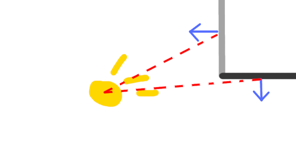
Looking at this picture we see a light source in yellow, and two walls in the top right. Intuitively the human brain knows which wall should be brighter. If we were to move the light source ever so slightly up, the bottom facing wall would be receiving almost no light at all.
This can be mathematically observed by noting the angle between the red (dashed) vectors and the blue (pointy) normal vectors. For the left facing wall, the angle is smaller than it is for the bottom facing wall. By calculating the sine of this angle, we can acquire a fairly accurate measure of the intensity of the light hitting the surface.
One way to reason through why this works is to think about the light as emitting photons in a constant radial density from its center. The more head-on a wall is facing the light source, the more densely those photons emitting from the light source will fall upon it.
Think about shining a flashlight directly on a wall, this is the brightest it will be, if you shine it so that the light hits at an angle, the light is more spread out, and thus is lower intensity.
Specular Light Is what artists refer to commonly as "highlights". It's the little white spots that show up on someone's nose, or in a light study done of a ball. These show up often in the real world, and so to include them in our simulation we have to figure out what causes them, or at least some way to simulate them.
The simplest way to imagine highlights or specular light is to imagine your friend shining a flashlight at a mirror (since every object is essentially a mirror or varying dullness). The spot of the mirror that shows up bright is the spot that you have to look at to look directly into the flashlight.
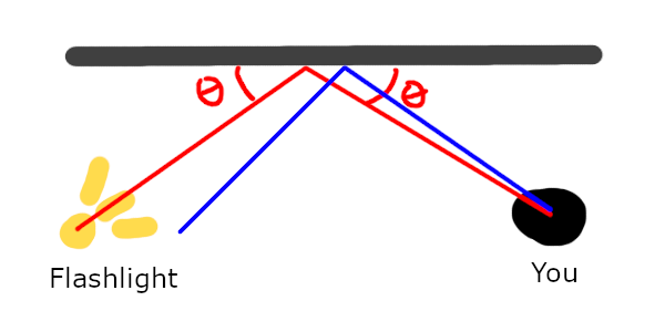
The spot where the reflection takes place is where the object will be the most bright. To capture this phenomenon, we must use math.
The gist of how we calculate the brightness of a given pixel is we figure out how close it is to the theoretical "maximum brightness spot" on the surface, by taking the dot product of it's reflected vector (seen in blue , or the one without angle labels in the picture) with the theoretical max brightness vector.
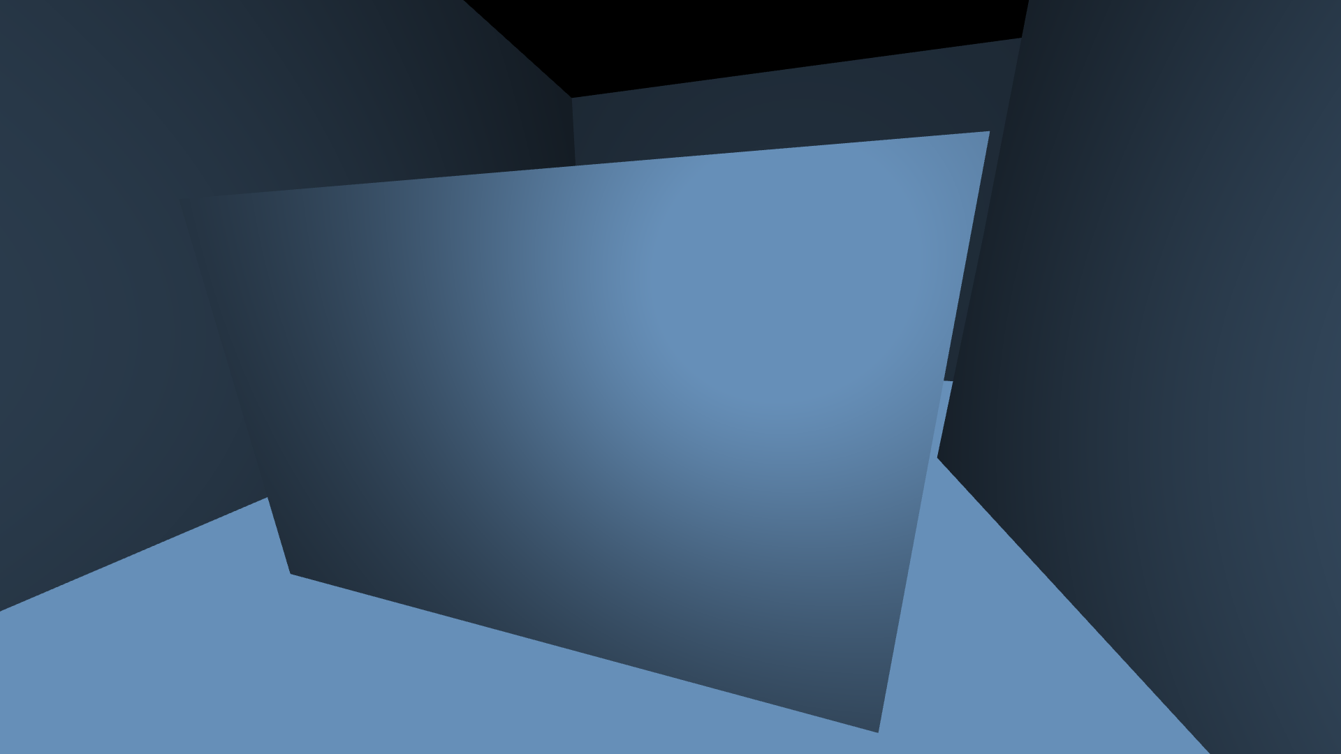
This dot product gives us a value between zero and one. But there is more we can do to this value. The brightness of this highlight should reduce as we get farther away from it, right? This is what is known as the inverse square law for light. To increase the accuracy of this we divide the intensity of that dot product by the square of the distance from the fragment to the light source. Then we multiply it by some scalar (found experimentally). This results in some nice highlights. Finally we sum the three values we just talked about to produce a light value for each pixel. The end result looks like this (screenshot from my engine).
Math Library
This is a feature which is not very glamorous, but I figured I would mention it anyway. The last time I wrote an OpenGL engine, I used glm, which is a linear algebra library designed for OpenGL. It works and is nice, but it almost feels a little bit like cheating. It allows you do us things like glm::lookat for calculating transform matrices, or generate a perspective projection matrix without ever looking at the math behind it. It effectively turns a lot of 3d graphics fundamentals into black boxes. This was not satsifying for me.So I wrote my own library. It has standard features, including 3d and 4d vectors and matrices. These are pretty straight forward to implement in terms of just multiplying vectors by matrices and calculating dot products. It's quite cathartic to implement things from math class in code and seeing them used in an application though.
The cool features that I had to do extra research on were the creating rotation and perspective matrices. There are plenty of easy to understand rotation matrices which can rotate vectors around cardinal axes, but I wanted to be able to rotate about an arbitrary axis.
This led me to wikipedia for quaternions. I'm honestly the wrong person to ask about this, as this is beyond my mathematical knowledge to some extent. I was simply a user of quaternions in this project, rather than the master of them. Apparently quaternions can be used to represent spatial orientation in 3d space. I used this wikipedia article along with patience to write a quaternion class complete with the ability to convert it to a matrix. This allowed me to create rotation matrices around arbitrary axes.
This is particularly useful when making a camera object, which, in a video game is usually controlled by a mouse doing both pitch and yaw. First the camera is pitched about the vertical axis, and then is rotated about its right-facing axis, which is effectively arbitrary.
The other feature that I had to research was perspective projection. I have made other projects in the past implementing perspective projection. The basic idea is captured in one sentence "An object moved twice as far away from you becomes twice as small". This is achieved by calculating screen coordinates by dividing x and y by the depth z. I have talked about this in my other blogs about minebike and. There is also a wikipedia article on it. This is fascinating to me and I love optics and vision in this sense.
In previous projects I had implemented this through algorithm, by simplying taking vectors and applying the above mentioned formula. However, as we found out with rotations, there is a much more succint way to do this using linear algebra. Meet the simple perspective projection matrix and by extension the OpenGL Projection Matrix which allows us to adjust aspect ration and fov, which is really nice for creating images just the way we desire. There's not much complicated about putting this matrix in my library. I pretty much just copied the matrix into it at this point and created a function for creating one. However understanding it is the real benefit. There's a great youtube video about this matrix if you are interested. I didn't really take the effor to fully grasp the fov and aspect ratio adjustments but the formulas are all there in my code.